Radio Frequency over Glass (RFoG) is a deep fiber network design in which the coax portion of the HFC network is replaced by a single-fiber, passive optical architecture (PON). Downstream and return path transmission uses different wavelengths to share the same fiber, typically 1,550 nm downstream and either 1,310 nm or 1,590/1610 nm upstream. The return path wavelength standard is expected to be 1610 nm, but early deployments have used 1590 nm. Using 1,590/1610 nm for the return path allows the fiber infrastructure to simultaneously support both RFoG and a standards-based PON, operating with 1,490 nm downstream and 1,310 nm return path wavelengths.
 * Advantages of RFoG service
RFoG delivers the same services as an RF/DOCSIS/HFC network, with the added benefit of improved noise performance and increased usable RF spectrum in both the downstream and return path directions. Both RFoG and HFC systems can concurrently operate out of the same headend/hub, making RFoG a good solution for node splitting and capacity increases on an existing network.
RFoG allows service providers to continue to leverage traditional HFC equipment and back-office applications with the new FTTP deployments. Cable operators can continue to rely on the existing provisioning and billing systems, CMTSplatforms, headend equipment, set-top boxes, conditional access technology, and cable modems while gaining benefits inherent with RFoG and FTTx. RFoG provides multiple benefits over traditional network architectures:
· Moredownstream spectrum. RFoG systems support 1 GHz and beyond, directly correlating to increased video and/or downstream data service support.
· More upstream bandwidth. RFoG's improved noise characteristics allow for the use of the full 5–42 MHz return path spectrum. Additionally, higher performance RFoG systems not only support DOCSIS 3.0 with bonding, but also enable 64 QAM upstream transmission in a DOCSIS 3.0 bonded channel, dramatically increasing return path bandwidth.
· Improved operational expenses. RFoG brings the benefits of a passive fiber topology. Removing active devices in the access network reduces overall power requirements as well as ongoing maintenance costs that would normally be needed for active elements like nodes and amplifiers.
Both cost savings and increased capacity for new services (revenue generating and/or competitive positioning) are driving the acceptance of RFoG as a cost-effective migration step on the path towards a 100% PON-based access network.
* How RFoG is implemented
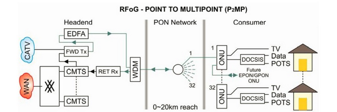
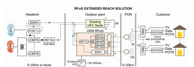
Just like with an HFC architecture, video controllers and data networking services are fed through a CMTS/edge router. These electrical signals are then converted to optical and transported via a 1550 nm wavelength through a wave division multiplexing (WDM) platform and a passive splitter to a fiber-optic micronode located at the customer premises. If necessary, an erbium-doped fiber amplifier (EDFA) can be used to boost the downstream optical signal to cover a greater distance.
The fiber-optic micronodes – which are also referred to as RFoG optical networking units (R-ONUs) –terminate the fiber connection and convert the traffic for delivery over the in-home network. Video traffic can be fed over coax to a set-top box, while voice and data traffic can be delivered to an embedded multimedia terminal adapter (eMTA), which connects to analog telephone lines over the subscriber’s internal phone wiring and to PCs via Ethernet or WiFi. The return path for voice, data, and video traffic is over a 1310 or 1590/1610 nm wavelength to a return path receiver, which converts the optical signal to RF and feeds it back into the CMTS and video controller. Although RFoG is providing a capacity increase, one undesired effect of the system is that more than one R-ONU can have the optical return path activated at the same time and at the same wavelength (for instance one R-ONU falsely triggered by ingress), thus an optical collision may occur (optical beating).
R-ONUs convert optical signals into electrical ones. This is done in place of the same function traditionally performed back at the higher-level serving area nodes in the HFC network. The RF infrastructure remains in place; the difference is that the fiber termination is moved from a fiber node to the customer premise. The R-ONU can be located at any type of customer premise: a single home, a business, a multi-tenant dwelling (MTU/MDU) or even the individual living units within an MTU.
When the time comes to migrate to the next phase in upgrading the network, the RFoG elements can remain in place while the provider rolls out the necessary components (OLTs and ONTs) for a full PON implementation.